After the completion of the design stage, those products are examined in terms of production methods, and necessary innovations which facilitate their processing/ molding are applied.
Then, production drawings are created for mass production. At this step, problems which may prevent production, may cause dimensional inconsistencies, deterioration of visual appearance, and thus delay of the product’s market launch or drop of product desirability by the customers are detected and solved in advance.
Thanks to our design engineering team that have manufacturing experience, we help you to bring your product into the market faster.
This phase consists of simulations and revisions made to produce the product more conveniently and cost-effectively after its 3D detailing is complete.
Moldability is particularly important in all steps starting from concept development for the parts that will be molded with plastic injection.
To give an example, a deep grain added onto the surface of the plastic part to improve the visual effect may complicate demolding / ejection (Figure 1).

Figure 1 - The grain that makes the demolding process difficult and insufficient draft angle
Or a wall that exceeds the overall wall-thickness in design may cause sink marks on the “A surface” of the product (Figure 2).

Figure 2 - Possible sink area
Another example is that the parting surfaces steepened due to part geometry might prevent molding by colliding with or scraping against each other.
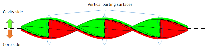
Figure 3 - Draft angles and vertical parting surfaces
As Tulga, we improve the 3D design before mold production in order to prevent such problems and more by examining draft angles, undercuts, parting line, sliders, areas where slider marks are acceptable, and sections that have problematic wall thicknesses which might prevent or slow down filling.
For the parts that will be produced by machining or other methods, we improve the mechanical design by checking the minimum radius, groove / pocket width, wall thickness and many other variables.
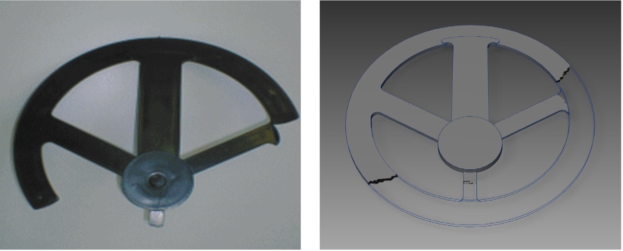
The quality of the molded piece is directly affected by production conditions. For example, the number of short-shots (Fig. 4) and sink marks increases in a part which is injected under low pressure while chemical degradation occurs in parts injected under high temperature.
Various input are entered into computer and the process is previewed in order to identify similar problems that may occur during serial molding. So, it is determined whether the injection conditions are within the optimum process window (Figure 5).

Figure 5 - Plastic injection process window
During simulation, several variables such as runner sizes, gate locations, filling simulation, filling time, cooling time, cycle time, injection time, air gaps, warpage, weld line locations, injection pressure, packing / holding pressure, injection temperature, cooling performance and many other critical variables are determined in advance with molding analysis software, and necessary improvements are made.

In order to produce and assemble the product after the design process, technical drawings are created according to the production methods.
Technical drawing is based on an objective common language between engineers and manufacturers. You can have various parts produced in different parts of the world, and you can still easily assemble them thanks to the production drawings prepared perfectly.
Creating accurate production drawings requires serious experience in production.

On the other hand, production drawings do not only consist of dimensioned 3 orthographic views. It should also contain engineering specifications such as partial or full sections, tolerances of form and location, dimensional tolerances, surface treatment marks, and surface roughness values etc.
We can prepare 2D drafting in AISI, ISO or DIN standards according to our customers’ request. If the product is composed of an assembly group, we prepare the drawings of the parts and assembly separately. We create the manufacturing drawings of the parts in ISO-E standards unless otherwise specified.
Tulga creates manufacturing drawings in accordance with TS2040, TS 1980, TS10849, TS11397, TS6700, TS7015, and TS10841 standards.